Dicing Sapphire Wafers by Cleaving Using the LatticeAx and FlipScribe
Introduction
Cleaving is a simple and fast technique used to prepare samples of silicon and other semiconductor materials, but sapphire, even though it is a single crystal, does not cleave well. Current methods for downsizing sapphire involve sawing and cleaving but yields are unsatisfactory due to fractures in unwanted directions and loss of material during the process. Laser scribing and cryogenic cooling are mentioned in literature as methods that can reduce unwanted fractures, delamination, chipping and loss of material but these methods are costly, time consuming and can present other undesired issues like edge quality and thermal damage due to temperature changes.
As cleaving is fast, low cost with no loss of material, several 3” sapphire wafers were acquired by LatticeGear to revisit cleaving of sapphire using two recently developed methods. These methods are differentiated from handheld scribing and cleaving because they integrate diamond indenting, scribing and cleaving into a mechanical platform. The “smart” mechanics (knobs, levers, dials) enable a repeatable process and remove variation in results based on the operator. It also allows for new test conditions that are not possible with handheld processes.
Cleaving explained.
Two steps are required to cleave a sample.
Step 1. Weak point creation
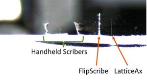
The weak point is a defect created on the sample. It will be the initiation point for the cleave. It is not possible to split a substrate into two pieces without first making a weak point using a diamond scriber or indenter. The weak point is made on the edge of the sample (Figure 1) and is very important as it defines the accuracy and quality of the cleave because the cleave propagates from the weak point. If the weak point is made at an angle, is wide, or causes fractures both accuracy and quality of the cleaved surface will be negatively effected.
Step 2. Cleaving
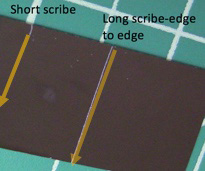
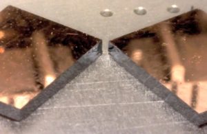
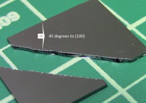
The second step in preparing a cleaved sample is cleaving. Cleaving occurs by creating stress on the weak point. The cleave is then initiated and propagates across the sample. If the sample is crystalline, the best weak point is short (Figure 2) as it initiates a cleave following a crystal plane. The resulting cross section will have a mirror finish (Figure 3). If the sample is amorphous, the sample will break but without a crystal plane, the cleave will propagate in the direction of the weak point but may not be straight unless a long scribe is made scribed across the entire desired line of cleavage (Figure 2). The resulting cross section will not have a mirror finish. This “long scribe” approach is also used on crystalline material when the line of cleavage needs to be counter to the crystal plane. Figure 4 shows a silicon sample cleaved at 45 degrees to the (100) crystal plane. Note that because the cleave is counter to the crystal plane the edge is rough. Cleaving can be done by splitting the sample in two with fingers, pins, pliers, or indenting and cleaving tool such as the LatticeAx.
Results
The two tools used in this study for creating the weak point and cleaving are the LatticeAx® and the FlipScribe®.
Method 1. Use of the LatticeAx® to cleanly cleave a 3” sapphire wafer
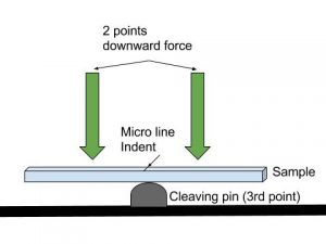
The LatticeAx combines weak point generation and cleaving into one tool. The weak point is made using a wedge-shaped diamond indenter. The microline indent is a short indent 750-1000mm long and 10 mm wide. After indenting, the sample is cleaved by putting downward force in 2 points at equal distance from the indent. (See Figure 5) (Watch how it is done).
A 3" sapphire wafer was cleanly cleaved using the LatticeAx’s standard, highly repeatable and accurate microline indent and cleave process. The LatticeAx’s microline indent was used to make the short indent at the edge of the wafer. This weak point then propagated along the crystal plane using the LatticeAx’s 3pt cleaving method. It resulted in very clean cross-section faces such as those required for photonics applications (Figure 6 and 7).
The process took approximately 5 minutes. As noted above, this process follows crystal planes and depending on how the devices are made, may not create cleaves that are normal to each other. To make rectangular samples, with edges parallel to and normal to the flat, one would need to use a method that uses a long scribe across the entire sample as shown in Figure 2.
The LatticeAx method is used to downsize from wafer to small pieces, especially when very clean, mirror finish edges are required.
Method 2. Use of the FlipScribe® to scribe, cleave and downsize a 3” sapphire wafer.
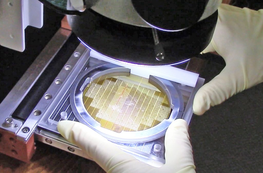
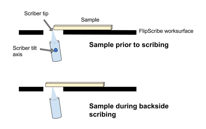
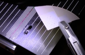
The FlipScribe is a scribing machine that scribes the backside of the sample while the operator views targets on the frontside of the sample. Samples are either manually guided or guided with the aid of sample holders, as seen in Figure 8, over the scriber tip. Figure 9 shows the position of the scriber contacting the backside of the sample during scribing. The scriber tilt and height are adjustable, this was found to be key to optimizing a process to prepare samples along lithography versus crystal planes.
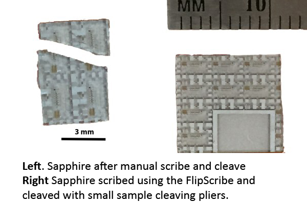
Note that for applications that require the wafer to be diced along the scribe line of the electronic structures the FlipScribe, scribing machine, is used to counter the cleave along the a-crystal planes of sapphire. Scribing will “force” the sample to break along the die scribe lines which are typically orthogonal. In Figure 10, the left image shows a sample cleaved after manually scribing with a pen style diamond scriber, note that the sample cleaves along a crystal plane which is not parallel to the lithography. To its right is a sample cleaved using the FlipScribe. This preparation resulted in a sample (10 mm on a side). This is typically desired for cross-sections and when testing the performance of a die. A weak point (long scribe line in this case) made with hand scriber is commonly too deep, large and destructive. If it is “too weak” the cleave naturally propagates through the strong, natural crystal plane. The cleave will always follow “the path of least resistance”. The FlipScribe scriber height and tilt can be optimized for the material and subsequently preset for a repeatable process. The holder secures (Figure 8) the sample assuring a shallow, thin and straight scribe line creating a “strong weak point” to initiate the cleave.
It shows that even though it is a difficult material, sapphire can be cleaved.
Cleaving Die from a 3” Sapphire Wafer.
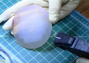
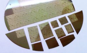
The 3” wafer, 470 µm thick, shown in Figure 8 was scribed and cleaved using the FlipScribe and a combination of the Cleanbreak Pliers and Small Sample Cleaving Pliers. In this case, a short scribe was made perpendicular to the flat as in this direction the crystal plane was parallel to the lithography. Parallel to the flat, long scribes were made to force the cleave to follow the lithography, not the sapphire crystal plane.
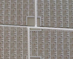
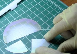
Scribing was performed on the FlipScribe using a custom designed 3” wafer holder. After scribing, the wafer was cleaved using the Cleanbreak Pliers as shown in Figure 11. Figure 12 shows the wafer after cleaving both parallel and perpendicular to the flat. To cleave the sapphire wafer into smaller samples, a small piece holder was used to grip the sample and make clean, straight scribes. Small die sized samples were cleaved using pliers optimized for small samples (Figure 13).
These results show that it is possible to cleave sapphire wafers without fractures and loss of material.
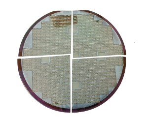
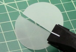
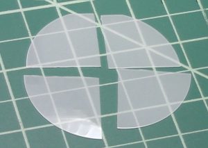
To verify this process could be repeated. Bare C-M plane sapphire wafers, 50.8mm in diameter and 420mm thick were purchased. The wafers were cleaved into quarters using the same method described above. The wafers were scribed using the FlipScribe and cleaved using Cleanbreak pliers.
Conclusion
With the right process and tools, sapphire can be cleaved cleanly and repeatedly. Both the LatticeAx and the FlipScribe are valuable additions to the laboratory when sapphire wafer downsizing for testing or cross-section analysis is required. The LatticeAx preparation produces mirror finish cleaved edges as the sample cleaves along a crystal plane. The FlipScribe backside scriber does not touch the sample frontside, it produces a clean break defined by the scribe line which can also be aligned with a surface target.
[wpdm_package id='5425']
